Micro Cluster Patent Technologies
MLL-1 micro laser line perforation real alternative for galvanometer scanner, cluster micro technology for hole pattern, perforation design, waves, zigzag or packages lines, cryptograms, company logos, holograms, anti counterfeiting, security paper, safety, bank note, metal sticker, printing, laminating, coating, credit cards, transparent films, holographic paper, cigarette, tipping, filter, aluminum foils, shrinkable films, tear tapes, labels, cardboards, bar or matrix codes, marking, scribing, jewelry, automotive, pharmacy, golf, smoking, chemical or medical product, electronics part, indicators, porosity contours or profiles, embossing, bioengineering, membrane, filtration, focus, holographic, hinge-lid, pack, hole, porous, hole, line, micron. Patent pending for process, device, product property DE102004012081.
LPM-1 micro laser perforation at wide web, large area, surface or whole material cluster treatment, cutting, welding, drilling, ablation, cleaning, melding, high power dual rotation laser beam splitter, twin multiplexer level, 4/6KW optical input, flexible hollow fibers, 200 output channels, Co2, Yag, Excimer, UV, emission. Material treatment and robotic handling for stainless steel, ceramic, aluminum, wafer, gold, glass, silver, brass, copper, titanium, diamonds, jewelry, silicon, solar, panel, photovoltaic, micromachining, slitting, rewinding, refining machines or stand along systems. Patent granted for process and device DE102004001327.
Nano Micro perforation or other material including surface treatment, electrostatic nano micro cluster perforation for cigarette, tipping, filter, packaging, plug wrap, Kraft, cement sack, bag, fine and other paper, silicon or other coatings, certain plastic films, laminates, porosity from 80 up to 2500 Coresta Units, from 20 down to 6 Gurley, hole sizes from 50 nm up to 100 microns, hole densities from 80-260 h/cm2, zone widths from 2.0-6.0 mm, up to 16,000,000 holes per Second, web speeds up to 500 m/min, web widths up to 2000 mm. Patent granted DE10328937.
Twin AC/AC, AC/DC frequency shift converter high power, high frequency, high voltage, ultra short mega peak current, electro static nano or micro cluster perforation, ignition, sparking, arc, cigarette, tipping, filter, fine, packaging, paper, plug-wrap, sack, bag, Kraft, food, plastic film, foil, textile, fabrics or other products, switching converter, compressor, emergency, train, ship or vessel power supply, generator, fuel cell, upward, downward, frequency shift switching unit, gas, slab, laser, diode, stack, fiber, beam, material, hybrid, plug-in, car, battery, lithium, Ion, renewable, energy, wind, solar, panel, technology, recycling, medical equipment, membrane filtration, robotic, photovoltaic, industrial automation, drives, IGBT, MOSFET, tube, rf, hv. Patent granted for process and device DE10328937.
Optical online OPSS-1 porovision scanning control system permeability cluster control for electrostatic or laser micro perforation machines, multiple color sensor head, spectral intensity, DSP, FPGA, CCD, line, precise, laser, position, material finger print detection, VIS wave length, opacity, defects, inspection, image control, scanner systems, process software, line, camera, vision control, filter, tipping, cigarette, book, packaging, magazine, bible, wall, Kraft, paper, carton, coffee, tea, food, co-extrusion foils, films, agriculture, cement, domestic or other moving fabrics or web material. Patent pending for process and device DE10251610. China patent granted 200310104764.
In-situ dyne or surface tension control ODSTM-1 at fast moving substrates, plastic, films, foils, tear tape, laminate, co-extrusion, BOPP, LLDPE, PE, PP, PVC, MOV, MOH, FEP, PET, OPP, PTFE, MPET, online, spectral, extinction, monolithic, sensor, analyzing, measurement, wave length, Raman, stray, beaming, water drop, angle, inspection, corona, plasma jet, laser, IR, NIR, scanning, wobbling, stray light, spectrometer, etc. Previous patent application DE19542289.
EU technology links
- http://www.ircnet.lu/matching/completerec.cfm?BBS_ID=20036&org=391
- Title: Micro-laser line perforation for web materials such as paper, metal or other substrates and laser application fields in industry (paper, packaging or cigarette industry) and research (Ref: 06 DE NRXE 0FGK )
- http://www.bit.or.at/irca/bbsshow8.php?ref1=06%20DE%20NRXE%200FGK&vQuelle=inna.at
- Micro-laser line perforation for web materials such as paper, metal or other substrates and laser application fields in industry (paper, packaging or cigarette industry) and research
- http://www.bit.or.at/irc/bbs-show.php?ref1=06%20DE%20NRXE%200FIX&vQuelle=&cc=&eoi=NO
- Optical online porosity scanning system
- http://www.enterpriseeuropenetwork.at/marktplatz/index.php?file=bbs-show.php&bbsref=06%20DE%20NRXE%200FIX&source=
- Optical online porosity scanning system
- http://www.enterpriseeuropenetwork.at/marktplatz/index.php?file=bbs-show.php&bbsref=06%20DE%20NRXE%200FIP&source=
- Dual, high-power, high- frequency switching unit for various perforation or other applications to increase operation frequencies and power levels
- http://www.enterpriseeuropenetwork.at/marktplatz/index.php?file=bbs-show.php&bbsref=06%20DE%20NRXE%200FGR&source=
- Off-line laser perforation system and machines for wide-web cigarette tip paper, packaging paper or other material sheets by using a high-power laser multiplexer
- http://www.enterpriseeuropenetwork.at/marktplatz/index.php?file=bbs-show.php&bbsref=06%20DE%20NRXE%200FGK&source=
- Micro-laser line perforation for web materials such as paper, metal or other substrates and laser application fields in industry (paper, packaging or cigarette industry) and research
Patent references
http://www.wikipatents.com/gb/2149092.html
http://www.wikipatents.com/de/3332886.html
http://www.wikipatents.com/de/2918283.html
http://www.freepatentsonline.com/EP0460369.html
http://www.freepatentsonline.com/7224447.html
http://v3.espacenet.com/publicationDetails/biblio?CC=EP&NR=0460369&KC=&FT=E
http://www.inpama.com/index.php?content=invention&id=18
http://www.inpama.com/index.php?content=invention&id=19
http://www.inpama.com/index.php?content=invention&id=20
http://www.inpama.com/index.php?content=invention&id=21
http://www.inpama.com/index.php?content=invention&id=22
http://www.inpama.com/index.php?content=invention&id=23
http://www.inpama.com/index.php?content=invention&id=24
https://www.patent-net.de/index.php?content=projekt&id=163
https://www.patent-net.de/index.php?content=projekt&id=213
https://www.patent-net.de/index.php?content=projekt&id=155
https://www.patent-net.de/index.php?content=projekt&id=156
https://www.patent-net.de/index.php?content=projekt&id=214
https://www.patent-net.de/index.php?content=projekt&id=157
https://www.patent-net.de/index.php?content=projekt&id=158
https://www.patent-net.de/index.php?content=projekt&id=287
PowerSourcing Links
- http://www.PowerSourcing.com/se/lasermicroholedrilling.htm
- http://www.PowerSourcing.com/se/laserscanning.htm
- http://www.PowerSourcing.com/se/laseroptics.htm
- http://www.PowerSourcing.com/sf/electricalpackaginglinedesign.htm
- http://www.PowerSourcing.com/sf/packaginglinedesignelectrical.htm
- http://www.PowerSourcing.com/se/paperproducts.htm
- http://www.PowerSourcing.com/se/coatedtreatedpaper.htm
- http://www.PowerSourcing.com/sf/microperforation.htm
- http://www.PowerSourcing.com/sf/lasermicromachining.htm
- http://www.PowerSourcing.com/se/machinetoolsinspectionqualitycontrol.htm
Opto Dynamic Surface Tension dyne control ODSTM-1 at fast moving plastic or packaging films, foils or other substrates
Patent application : DE19542289
Patent classification: G 01 L 1/24
download ODSTM-1-PATENT
patent download http://www.microperforation.com/englishengineerreport.html
Dyn control
Described is a method and device for optical inline tough less surface
tension control ODSTM-1 by which the fast moving substrate runs through the
measuring gap. Its transmitted with a chromatic beam and spectral selected
light source were two optical channels are displaced and polarized by 90 degree
to each other. Both optical axles are precise and motor driven shift able in
certain angles from 25 up to 65 degree. The spectral light photons, transmission,
extinction, absorption grades are detectable by two optical CCD imagine vision
devices which are integrate in the sensor case on the other side of the
substrate.
Material
Moving substrates means plastic foils, flexible, high-tech films, laminate, tear tapes, coating, bonding, labeling, co-extrusion, BOPP, LDPE, LLDPE, HDPE, MDPE, MAS, MEV, PET, FEP, PP, PE, PS, PO, EVA, PTFE, PVC, PTFE, DPC, BOPS, Vinyl, Polyester, Wrapping, Olefin, self-adhesive tape, high strength, cross-laminated, adhesive coated films, reflective or magnetic sheeting, automotive tape products, inkjet media, Polyethylenex, heat sealing, sewing of plastic film, pressure sensitive tapes for the entertainment industry, graphic and specialty arts for general industrial and electrical applications, building or engineering industry, photographs, masking or printable plastic films, flat or corrugated rigid foamed thermoplastic sheets, polycarbonate, acrylic, PETG.
Extruded or polished cellulose, optical grade polycarbonate, sheets for IR or laser protection, welding filter grade sheets, films for video, imaging, capacitor or thermo transfer applications, foamed polypropylene film with decorative ribbons, binary-oriented polystyrene sheets, multi layer co-extruded film, high impact PVC and PETG, polyimide film, tape and flat films for aerospace automotive medical agriculture marine automotive household commercial domestic construction industry, municipal and leisure applications, clear matt semi-matt finishes or colored, micro-porous membranes for use in alkaline lithium batteries, fuel cells and filtration equipment. By gauges from 10µ to 100µ, fabric widths up to 10,000 mm and web speeds up to 18 meters per second.
Optical properties
Material specific wavelength selection between 1200-1800nm, material specific finger prints, molecular spectral properties, transmission grades, optical angle scanning, Lambert Beersche law determining, ultra low level stray scatter light detection, polarization, slot diaphragms, transverse displacements control the light beams along/far from the optical X and Y axes. The results are extreme scattering, diffraction, NIR, IR, stray light photons generation into the layer areas at both sides of the moving substrate.
Their reflected and transmitted light intensities enables the determination by defined formulas and data matrixes the surface tension values in ranges from 28-62mN/m which are direct associate and bond to real static values for Statistical Quality Control (SQC).
And this entirely independent of the material specific influences as like surface consistency, thickness, density, weight, opacity, coherence, filling, stretching, shrinkage, structure, co-extrusion, polar grouping, temperature, intrinsic motivation or viscosity, hydrophobia, hydrophilic molecules, hydrogen, photonics, mol mass, moisture, water steam proof, bi-layer, polymer, patterning, nanostructure, irradiation, isotopic, catalyst, multi atomic, coherence, absorption, photo mask effect, roentgen, X-ray, radiation, resonance bands, REM, TEM, FIC, IEC, ESCA electron spectroscopy for chemical analysis ASTM or ATR method, property, ellipsometry, opto-acoustic photonic liquid effects, pre material treatment as corona, plasma, flam treatment.
Specific information by website links and patent resources.
Introduction ODSTM-1
Non-contact, real-time and optical online operation surface-tension or
surface-energy dyn - control systems for running webs as like plastic films
in general, coatings, laminates etc. does not exist world wide.
Due to the broad application field of surface-treated or surface-non-treated webs of plastic film, non-woven, fabrics, laminates or coated paper, there is unimaginable market potential here in respect of the inline process measuring of the surface tension - dyn - and an inline control of the dyn treatment level and moderate quality control.
A large number of companies are serious interest in project cooperation, system development, prototyping, manufacturing, testing, and world wide sales, system purchasing and licensing in order of the working principle of the ODSTM-1 Process Measuring System and former Patent application DE19542289.
Significant here are the recent relatively new applications which, without exception, concern the static detection and determination of the surface-tension value with sequentially applied liquid drops and imaging system. This includes: DE4102990, DE3808860, EP0237221 and DE3410778. Further information mention in the application document.
Actual situation of the ODSTM-1 development project
Further information concerning publications, patents and engineering reports are specified in the below applications. Spectral measurements as well the feasibility study with well known optical institutes are positive finished. Furthermore some significant modifications and breakthroughs of the base ODSTM-1 measuring process in using state-of-the-art monolithic spectrometers and PC support.
Specific information of the current project status on request.
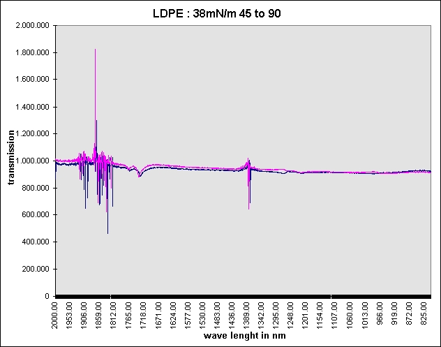
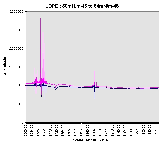
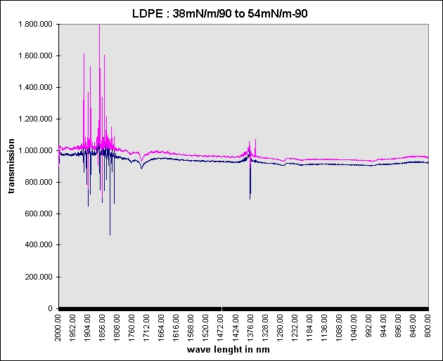
Regarding the ODSTM-1 development and project status together with a well known optical institute specific measurements with monolithic spectrometers wave ranges of 1200 1600 nm are successful done all measurements are based on the detection principle which are described in the former patent application DE19542289 used non treated LDPE films in 15 and 30 µm thicknesses by 28 mN/m base level comparison measurements of LDPE films with one side corona treated of 38, 48, 52, 60 mN/m test results are positive with good prospects for further developments.
Test results at our website http://www.microperforation.com/odstm-1-optical-dyn-control.html
Current publications and copyrights targets to the ODSTM-1 subject, contents and physical working method
- Schichtbetrieb - Anforderungen an Schichtdickenmessung in der Mikro- und Nanotechnik : MessTec & Automation 3/2003, Prof. Peter Pokrovski
- Optische Schichten mit ultrahydrophoben und streuarmen Eigenschaften : Photonik 4/2002, K.Reihs Surface Nanotechnologies GmbH, A.Duparre, Fraunhofer IOF
- Anforderungen an Spektralmessgeraete für DWDM-Systeme : Photonik 4/2002, Laurant Begin, Jim Nerschook, NetTest, Utica, NY, USA
- Nanoporöse Polymerfilme als kostengünstige und zugleich hochwertige Antireflexbeschichtungen : Photonik 4/2002, Dr. Stefan Walheim, FZ-Karlsruhe, Institut für Nanotechnologie
- JURCA Optoelektronik GmbH : Hochgenaue schnelle Schichtdickenbestimmung mit Weißlichtinterferometrie, (Highly-accurate and quick layer-thickness measuring with white light interferometry) Sensor Magazine 1/2000
- JURCA Optoelektronik GmbH - Dr. Gerd Jakob : Koaxiale interferometrische Schichtdickenmessung, Photonik 9/2000
- Datron-Meßtechnik GmbH : Mikrowellensensor für Weg- und Geschwindigkeitsmessung, (Micro-wave sensor for distance and speed measuring) Meßtech 2/2000
- Franz-Patat-Zentrum : Oberflächenbehandlung - Neues höchstens im Labor, (Surface treatment the latest, only in the laboratory) PKV-Magazine 3/2000
- Institut für Kunststoffverarbeitung (Institute for Plastic Processing) Aachen IKV : Folienextrusion - Ergänzendes Nebeneinander von Gieß- und Flachfolienverfahren, page 39, (Film extrusion complementary use of casting and flat film techniques) PKV-Magazine 12/1999
- In-Line Nahinfrarot-Spektroskopie bei der Kunststoffextrusion : publication at GIT-Labor-Fachzeitschrift 12/2000, Dipl.Phys. Thomas Rohe, Dipl.Ing. Sabine Kölle - FHG für Chemische Technologie ( ICT )
- Smart Priming : publication at coating 12/2000 by Dr. Michael Bauer, Dr. Martin Kunz
- Semiconductor Metrology: Will Photonics Measure Up ?Scatterometry, ellipsometry and optoacoustic techniques represent photonics in metrology toolbox of next-generation integrated circuits : publication at Photonics Spectra December 2000 by Alain C.Diebold - International Sematech senior fellow
- Enercon : Reprint from Flexo May 1988 : Statistical Quality Control ( SQC ) Applied to Corona Treating, by David Markgraf Enercon : Corona Treatment - an overview, by David Markgraf, Enercon Industries Corp.
- Light Scattering Measures Subangstrom Roughness - by Laurel M. Sheppard, Photonics Spectra 9/1999
- Basis Weight, Sensor for Sheet and Film Products : by Honeywell-Measurex, Coating Magazine 11/1998
- A comparison of 3D static light-scattering experiments with Monte Carlo simulations : Institute for Anorganic und Physical Chemistry of the Bremen University, IOP-Publishing Ltd. 32/1999
- Was kann Oberflächenanalyse ? : Dr.J.Goschnick, coating 3/2000
- Corona Technologie : Patentinformationen, Anwendungen, Mechanismen : Dr. Ralf Quack, coating 3/2000
- WO99/23479 : Reflectometer
- WO98/06999 : Method and Device for measuring the thickness of an insulating coating
- US5590560 : Apparatus for measuring viscosity or thickness, surface tension and surface dilational elasticity
- EP0225590 : Verfahren und Vorrichtung zur Bestimmung von Dicken- und/oder Orientierungsänderungen innerhalb einer optisch aktiven Materialbahn (Method and device for the measurement of thickness changes and/or orientation changes within an optically active material web)
- Coating magazine 2-2004, Coronabehandlung von Polymerfolien, Nachweismethoden, Einflussfaktoren und On line-Kontrolle, Dr.-Ing. Andreas Kiesow, Dr. Jürgen Meinhardt, Prof. Dr. Andreas Heilmann
Extracts of the publications and patent applications relating
to the state-of-the-art of STATIC surface tension measurement have been
compiled.
Significant here are the recent relatively new applications which, without
exception, concern the static detection and determination of the
surface-tension value with sequentially applied liquid drops and imaging
system.
This includes: DE4102990, DE3808860, EP0237221 and DE3410778.
Further information are mentioned in the application document.
Key datas of Opto Dynamic
Surface-Tension Measuring system ODSTM-1
· web widths : up to 6000 mm
· web speeds : up to 600 m/min
· substrates : PE, PP, HDPE, LDPE, PET, EVA, BOPP, etc.
· surface-tension measuring range : 30 - 55 mNm
· resolution, respectively, reproduction : +/- 0.5 mNm
· single-sided or double-sided measurement of the treated or untreated sides
of the film
· IR wavelength range : 1200 nm - 1800 nm
· mode of operation : dual scattered-light/multiple-sensor system with
variable wavelengths in transmission mode
· measuring method : similar to ellipsometry
· measuring gap : approx. 5 - 20 mm
· stationary and/or web-traversing measuring head
· optical fibre waveguide feed to measuring head system
· spatially remote, highly-stable IR light source with beam processing
· wavelength variation via a monolithic optical converter
· industrial PC, multiple-processor system, data recording, data analysis,
product documentation, statistics, etc.
· actual-value output : analogue 0 - 10 V via optical fiber or serial RS 232,
etc.
SUMMARY
Described is a method and device for opto
dynamic in-line surface-tension measurement in which a substrate web running
vertically through a measuring gap is subjected to a chromatic light
transmission from two opto-channels displaced by 90° to each other. This light
transmission is detectable by two optical detection systems located on the
other side of the web. Material-specific wavelength selection, light
transmission angle changes, polarization slot diaphragms and transverse
displacements of the light beam feeder along the optical X-axis result in
extreme scattering and diffraction of the IR light photons in the boundary
layer area on both sides of the sub nano layer within the substrate web. Their
transmitted light intensity enables, after detection and evaluation, the
determination of a direct relationship to the absolute surface tension.
And this entirely independent of the material-specific influences like:
material and surface consistency, crystallinity, thickness, density, structure,
polar grouping, temperature and type of pre-treatment.
LPDE BOPP films - spectral properties by different transmission relation


Revised content of patent application DE19542289 - copyright Werner Grosse
The invention concerns a method and device
for opto dynamic, i.e. a non-contact, in-line surface-tension surface-energy
measurement for running substrates whereby the detection can be in the
transverse-direction or in the running-direction of the web.
In the context of this invention, running substrates or moved web material is
to be especially understood as being plastic films like PE, PP, LDPE, HDPE,
LLDPE, EVOH, PTFE, PET, PS, PMMA, PBMA, PVC, PA and also laminated or coated
film or paper webs which still show a measurable optical transmission in the
wavelength range of 200 to 8000 nm.
A higher material wetting capacity, respectively, a higher material adhesion capacity, which can be achieved by increasing the surface tension, is demanded in many application cases for better printability, coatability or adherence capacity during the manufacture, finishing, printing and processing of running substrate webs.
Technical literature which references can be made in respect of these complex physical relationships, include the following:
- J.Hansmann : Korona Oberflächenbehandlung zur Haftungsverbesserung, Sonderdruck Papier und Kunststoffverarbeiter 4/7/81 (Corona surface treatment for improved adhesion for special-print paper and plastics processor)
- J.Reif: Physical interaction mechanisms between laser radiation and the surface of transparent materials, lecture by Laser Colloqium Erlangen 6.12.1989
- Zafiropulos: Laser Ellipsometry, Laser Magazine 5/91
- Prof.Dr.-Ing. L.Dorn: Klebeflächen Untersuchungen mittels Rastertunnelmikroskop Investigation of adhesion surfaces by way of a scanning tunnel microscope)
- Dr.Gerstenberg: Korona-Vorbehandlung zur Erzielung von Benetzung und Haftung, coating (Corona pre-treatment for improved wetting and adhesion of coatings)
- B.Johs: real-time monitoring and controlling with multi-wavelength ellipsometry, ICSE 93
- In simple terms, surface tension, respectively, surface energy, is to be understood as being a physically measurable tensile stress which can be determined by the molecules in the boundary layer of the substrate and the adhesion strength of these molecules. This tensile stress, which is to be regarded as both energy stress and mechanical stress, is defined by the physical unit millinewton/m (mN/m), formerly also dyn/cm.
For the purpose of
simplification, the term surface tension is also used for surface-tension
energy in the following text.
As example, a few surface-tension base values of different
substrates are: PS = 33 mN/m, PA = 43 mN/m, PE = 31mN/m, PP = 29 mN/m. In
comparison, the values for a few liquids are : Water = 72 mN/m, Methanol = 22
mN/m and Tulol = 28 mN/m.
An increase in the surface tension, or a 'molecular
roughening', of the material surfaces is currently achieved with industrial
pre-treatment methods using solvents, primer, plasma, UV radiation,
flame-treatment, ozone gassing and corona.
A major quality criterion for the product resulting from the finishing or
manufacturing process, and this is totally independent of the pre-treatment
method used, is the consistent compliance with material-specific and productspecific
surface tension specifications for the pre-treatment process. This is not only
applicable for a best possible homogenous surface formation but also for a
short-term and long-term achievement of a narrow surface-tension range which
can be extremely influenced by the external and material factors, type of
pre-treatment and treatment changes. For example, depending on the use of
solvent or water-soluble inks for the printing, the (surface-tension) base
range of extruded LDPE films after the increase in their surface tension is 36-46 mN/m, whereby their variations can easily be +/- 3 mN/m and more.
The current state of the art involves the use of various static, i.e. not
in-line and mostly optical, measuring methods for the detection of the surface
tension for web-shaped or piece materials, e.g. with test inks as per
ASTM-D2578-67, as per the contact angle measuring method, by way of Rheology
for liquids, the ESCA electron spectroscopy for chemical analysis or the ATR
method. The measuring of these methods always occurs according to the off-line
principle, which means that samples must be taken during machine stop or
during the running production process, with subsequent surface-tension
measuring in order to be able to subsequently adapt to the desired
pre-treatment level, respectively, to try to achieve the specified
surface-tension values in this way.
The significant printed patent specifications and published patent application specifications under the IPC G01 B 11/30 to be mentioned hereto are the : EP0032710 A1/B1, EP0237221, DE2804975 Al, EP0134930 A1, DE3406191 Al, DE3808860 A1, DE3410778 A1, DE4102990 A1, DE3105752 A1, DE2537343. From the application DE2225946, it is also known that there is an attempt to achieve a differential measurement of the surface tension with two optical devices in in-line mode before and after the pre-treatment, however, their mode of operation is not explained. The published patent application specification DE 38.25.416 A1 describes a dynamic application method of test inks on running webs in order to obtain an in-line measurement of the surface tension.
In respect of optical in-line porosity measurement on running webs, the EP0608544 A2 and DE4302137 A 1 contain descriptions of optical transmission methods with which material independent measurement values can be derived as a function of the gas permeability by way of a horizontal measuring head displacement along the optical axis of the traversing device and over large web widths. Also known are traversing and in-line working measuring systems, for the web materials mentioned at the beginning, with which numerous material-specific characteristics can be measured in the optical transmission mode, but a surface-tension measurement or mathematical derivation is not possible.
The static and both dynamic working methods do not full fill the specified requirements because of the production-related performance targets and consequently the set criteria for non-contact in-line surface-tension measurement on running substrates with absolutely no measurement result influence from material and surface consistency, crystillanity, thickness, density, structure, polar formation, temperature, type of pre-treatment and at web speeds of up to 600 m/min and web width of up to 6000 mm.
The mentioned measuring methods also involve the disadvantage of possible machine standstill times for sample-taking or the occurrence of undesired surface-tension fluctuations between the test intervals. Furthermore, a direct process control or regulation, CIM integration and product certification are not possible because the systems work off-line.
The cardinal requirements for a non-contact and inline working measuring system can be summarized from the above introductory description as follows:
- useability for web materials like PE, PP, LDPE, HDPE, LLDPE, EVOH, PTFE, PET, PS, PMMA, PBMA, PVC, PA, laminated or coated film or paper
- measurement-independence from material and surface consistency, crystallinity, thickness, density, structure, polar grouping, temperature and type of pre-treatment
- web speeds of up to 600 m/min and web widths of up to 6000 mm
- in-line, real-time and non-contact working measuring method
- single measuring head
- surface-tension measuring range of 30 to 60 mN/m with a reproducibility of +/- 1 mN/m
- can be integrated into existing traversing systems
- computer operation and machine interfacing
- insensitive to external influences like dust, vapours, external light, mechanic shock, etc.
- very low maintenance requirement
- absolute reliability
- easy-to-calibrate
- The invention therefore involves the task of describing a method and device which can best-possibly fulfil the described requirement profile for opto-dynamic, i.e. a non-contact, surface-tension measurement.
The invention method for opto-dynamic surface-tension measuring on running substrates fulfils the set requirement by way of the features of the patent main claim 1.
According to this, the substrate web which is to be measured and running through the measuring gap of the system is subjected to a chromatic light transmission via two optical channels which are displaced by 90° to each other. This light transmission can be detected on the other side of the web by two optically identical detection systems. A transverse displacement of both light spray or detector units along the optical axis makes it possible to generate optical scattering and diffraction in the boundary layer area of the substrate by way of extreme beam angle displacement. After the evaluation of their captured light photons and their intensity with a conventional PC, it is possible to determine a direct relationship to the surface tension, independent of the aforementioned material influences.
The invention has confirmed that a two-channel, by 90° displaced, optical transmission through the running web material and extreme X-axis displacement of the beam angle, both in the horizontal and vertical direction, and at different wavelengths are necessary in order to be able to generate, detect and evaluate the desired scattering and diffraction effects in the two-sided boundary layer and sub-nano area. It is only the combination of horizontal and vertical beam path guidance, beam penetration angle change and the wavelength-specific selection for the used substrate which makes it possible to eliminate the material-specific influences so that a measurement value which has a clear relationship to the physical surface tension can be obtained during the optical transmission through the boundary areas and the polar groups located there.
This occurs using a relative measuring method via the generation of differences between two different surface-tension values with material-identical substrates. It was on the basis of these fundamental findings that the invention-related opto dynamical surface-tension measurement method and device for running substrates, which ideally full fill the aforementioned requirements and make the use of an in-line system possible, was developed.
A further important advantage of the invention-related measuring method is that the entire optical arrangement can be integrated in a single measuring head housing and can therefore be mounted onto an existing traversing system and be technically incorporated into the process control system. It is similarly possible to also operate the measuring head system automatically on extrusion or pre-treatment machinery, to incorporate it into the control processes of such machinery and to make possible an in-line certification for the substrate products produced in such a way. This is a further advantage of the invention-related method which opens up totally new dimensions in a production and economic sense.
The aforementioned requirement is also fulfilled by a device for opto-dynamic surface-tension measurement on running substrates with the features of patent claim 7.
According to this, the device is designed so that a single wavelength tune able light source unit supplies two optically identical channels which make possible a transmission in a vertical and horizontal position via two slot diffusers for the substrate web running through the measuring gap. Both optical channels can be geometrically displaced in the X and Y direction in respect to the detector units which are located on the other side of the web and arranged on the optical axes. The light photons falling into the optical lens arrangement in the detector unit are captured, bundled and focus onto photo-sensitive detectors. After their electrical pre-amplification, the signal analysis and measurement value determination occur with a conventional PC which also performs all the control tasks for the wavelength setting, X-displacement of the optical axis and system calibration.
There are now various ways to lay out and further-develop the system of this invention in an advantageous way. In this respect, reference is made to the designs described in the patent claims 1 - 15 and also to the following explanation of a design example of the invention by way of the drawings.
In conjunction with the explanation of the preferred design example of the invention and by way of the drawing, the generally preferred layout of the system is also explained.
The drawings and the additional diagrams specifically show :
- Fig. 1 the overall view of the surface-tension measuring device
- Fig. 2 the optical illustration of the X and Y slot diffusers on the photosensitive detectors in the case of optical axes equality
- Fig. 3 the optical illustration of the X and Y slot diffusers on the photosensitive detectors in the case of optical axes displacement
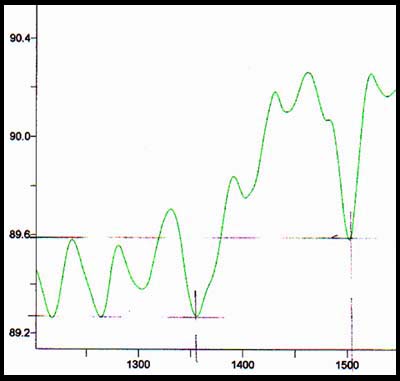
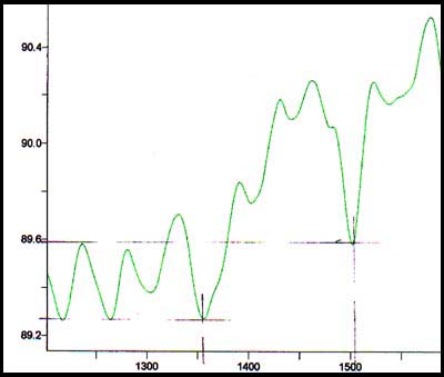
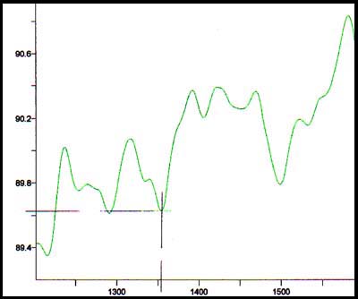
- Fig. 4 a diagram of the tension profile and the transmissions distribution for the determination of the surface tension of PP film
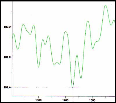
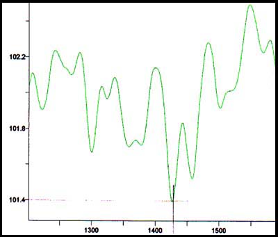
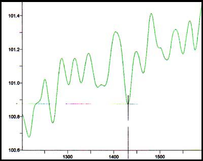
- Fig. 5 a diagram of the tension profile and the transmissions distribution for the determination of the surface tension of PE film.
- Fig. 6 - 11 diagrams about the spectral range, differences in the surface-tension values and the properties with different transmission criteria
The following first explains the device design and its fundamental mode of operation in order to thereafter provide a detailed explanation of the measuring method and the determination of the surface-tension values for running substrate webs.
Fig. 1 illustrates the entire surface-tension measuring device for running substrate. The light source device 1 essentially consists of an industrial broadband light source 4 (e.g. the combination of deuterium, halogen and IR lamps and the voltage supply and control unit 5). The join light beam path is aligned via a lens system 6 and polarization filter 7 onto the acousto-optic filter 8. The HF generator 9 for e.g. 10 - 100 MHz makes an infinitely variable wavelength tuning in the range from 200 nm to 5000 nm possible.
It is similarly possible to perform the detection at specific wavelengths with broadband or narrow band illumination in the IR wavelength range of, for example, 1200 - 1800 nm and monolithic spectrometers in order to replace the expensive acousto-optic converters.
The coupling-out of the beam occurs via a polarization filter 7 with its following beam splitter 10 for the generation of two optical channels, the beams of which are coupled into the broadband optic fiber bundles 12 and 13 via the two lenses 11.
In the beam feeder housing 2 of the measuring head, the coupling-in of the two optical channels occurs via the connected optic fiber bundles 12 and 13. The light beam from these is then projected via the lenses 14 onto the two vertically 16 and horizontally 17 arranged slot diffusers to the web 22 running vertically through the measuring gap 31. For the axis-distant capture of the light photons on the opposite web side there are large collection lenses 18 located on the optical X and Y axes. These are cascaded with smaller lenses in the direction of the detectors 20. The photosensitive detectors 20, located on the base plate 21, can be broadband photodiodes, photodiode arrays, CCD lines or image converters. For the coverage of the broad wavelength range of 200 - 2000 nm, it has proven advantageous to select the detectors 20 according to their spectral sensitivity for two wavelength ranges and use them as pairs.
The measurement gap 31 preferably has a width of 10 mm so that a sufficiently large clearance remains for the web 22 running through it even in the case of inexact positioning, centre-guidance or position movement. For ease of illustration, the mechanical displacement elements for the X-displacement 23 and 24 of both optical channels to the mid-axes 32 and 33 are not shown in Fig. 1 and 2. A very important measurement-related aspect here is the optical detector arrangement 20 which is positioned far outside of the actual focal points 29 so that the axes-distant and transmitted light photons resulting from the scattered transmission and diffraction at the boundary area of the running web can be mapped on the detectors.
Fig. 2 shows the pillow shape 34 of the first optical channel at detector 20 produced by the vertical slot diffuser 16 and the optical axis of the beam feeder unit 32 and the detectors 33. Analogue hereto, the same figure shows the optical image 35 of the horizontally arranged second channel at detector 20 in the case of axis equality 32 and 33.
An X-displacement of beam feeder unit 32 axis to detector axis 33, whereby preferably the detector unit is moved relative to the beamer feeder, results in an optically distorted image in the vertical 36 and horizontal 37 direction as can be seen in figure 3. The image distortion generated with the invention measuring methods result from a combination of the vertical and horizontal slot diffuser geometries and optical x-axis displacement of the detectors far outside of the lens focal point 29.
From various production applications and the aforementioned patent applications it is known that a selection of the material-specific characteristics of the running substrates at different wavelengths, the so-called finger printing, is possible. In this measurement method, this fundamental finding has led to the wavelength selection combined with the optical X-axis displacement being used for the compensation of the substrate characteristics in order to be able to determine the surface-tension value without influence from the material criteria.
The diagrams in Fig. 4 use, as an example, two material-identical PP films 38 and 39 with different surface tensions of 37 mN/m respectively 43 mN/m to illustrate the transmission values detected at the same wavelength and with photo-sensitive sensors. The lower ordinate shows the optical transmittance of both substrates 38 and 39 as a function of a one-sided axis displacement between 32 and 33, their optical axis coverage being defined in items 32 and 33. It can be clearly seen that the PP films 38 and 39, which are identical in material but have different surface-tension values, experience a value difference via the optical axis displacement whereby their substituted area integral of 40 shows the difference between the surface-tension values of 37mN/m to 43mN/m as a surface-tension value change. The displacement value, respectively the displacement direction to the right is shown on the axis.
Figure 5 make analogue use of two example PE films 41 and 42 having surface-tension values of 36 mN/m and 42 mN/m to illustrate the area integral 43 obtained as a difference of the surface value after the substitution.
The electrical circuit of the optical detectors, which can consist of individual photodiodes, photodiode arrays or CCD lines, is technically well-known and therefore not further illustrated. Their electrical coupling to a conventional PC by way of AD converter cards and/or multiprocessor cards also requires no further explanation.
The signal analysis and the difference generation are also dealt with in more depth in the following explanatory part.
As already stated in the introductory part, it is known according to the invention that two by 90° displaced optical substrate transmissions and their beam displacement along the optical x-axis generate scattering and diffraction effects on both sides of the boundary layer area which are material-specifically dependent on the used wavelength. The light quantum transmitted and detected in this way allow, after the signal conditioning, an amount-related determination of the relative measurement value of the surface tension. To simplify this device description, all mechanical design details and information on the traversing device for the left and right displacements 23 of the optical X-axes 27/28 are not further described because their fundamental mode of operation is assumed to be generally known.
The transmission properties, developed with the invention measuring method, and its derivations for the determination can be explained, from a physical and light quantum point of view, as follows:
- The wavelength-dependent transmission change in optically trans massive substrates 22 produces a material-specific transmission property, the so-called finger prints, which is generally known and technically used for numerous applications. For the invention method, the wavelength change occurs in a range from 200 nm to 8000 nm by way of a broadband light source 4 and a tune able acousto-optic filter 8.
- As we know from the ellipsometric measuring method for transparent plastic films, optically rotated and polarized beam paths make the mathematical thickness determination of these running substrates possible. For the method described here, the polarization filters 7 have the task of beam coupling and decoupling for the acousto-optic filter 8. An optical and by 90° rotated transmission of the running substrates 22 is verified via the two channels 12 and 13 and the longitudinal and transverse slot diffusers 17. This design allows the longitudinal and transverse oriented material formation, as it often occurs in the case of biaxial films, coated webs or multi-layers, to be taken into account in terms of technical detection.
- Special slot diffusers 16 and 17 produce extreme light scattering at their edges and consequently the associated changes in the beam angle by way of the light photons very distant from the optical axis line 27/28/32/33. These light scattering effects are taken into account and used, in part, in various industrial methods for the technical measurement of brightness, opacity, smoothness, divergence, opacity or porosity of transmission materials. The light scattering transmitted in the two optical channels during the coupling and decoupling in the running substrate 22 results in adsorption and diffusion appearance at their boundary surfaces. The investigations of the light scattering with chromatic light has shown, contrary to the general wavelength theory, that changes in molecular structure can be optically proven and that these are smaller than the used wavelength by a factor of 1000. This means that for a wavelength of 400 nm, for example, it is possible to optically detect "molecular" roughness of < 400 pm in the boundary layer area of the respective material side. The boundary layer areas responsible for the surface tension, material adhesion and polar groups range between 10 to 200 angstroms, equivalent to 10 to 20 nm.
- With this special geometry of the material transmission, the transmitted light quantum experience an easier material transmission in the case of changes in the one-sided or two-sided 'molecular roughening' in the boundary layer area and an associated surface tension increase and this results in a greater light quantum yield on the detector side. This is the only way in which the practical results - which allow a direct correlation to the surface-tension difference 40 and 43 and this totally independent of material/surface consistency, crystallinity, thickness, density, structure, polar grouping, temperature or the type of pre-treatment - can be interpreted.
- The transmission increases described and used for this method are especially pronounced when the used wavelength is close or equal to the resonance point of the web substrate, i.e. a greatly reduced optical transmission as opaqueness occurs and a sensory detection takes place far outside of the lens focal point. These light quantum related resonance points are assigned material-specifically and only change insignificantly for the running web during the running production or finishing process as the practical results show.
- When one material side has higher surface-tension values than the other, this results in detection differences which, after the evaluation, are proportional to the difference of the surface-tension values.
Further test series with the invention method show that sufficiently large quantities of transmitted light quantum can be released with the described device and the described optical X-axis displacement and its associated scattering and diffraction effects in the sub nano layer of the boundary layer area of the substrate web 22.
As this method is based on a relative measurement method, it is necessary to determine the desired surface-tension values via a correlation or comparison measurement using the same substrate types of type groups with lower and higher surface-tension values and a two-point method.
Based on that necessary explanations, the two-point calibration of the opto-dynamic method can be summarized by following steps :
- in the first calibration step, the substrate type (to be subsequently dynamically measured) with a known but low surface tension e.g. a PP film 38 with 37mN/m is placed in the measuring gap on a special device and statically detected
- this is followed by the determination of the resonance point by way of the wavelength variation in the range of, for example, 200 nm to 8000 nm using the acusto-optical filter 8 for both optical channels and their photo-sensitive detectors and appropriate signal conditioning which allows a value-related evaluation with a PC
- the optical axes 27/28/32 and 33 are identical during the first wavelength wobbling procedure
- the described axis displacement to the right side in the X-direction up to point 44 occurs during the second wobbling procedure
- analogue to this, the axis displacement to the left side in the X-direction occurs during the third wobbling procedure
- the material-specific resonance point, which is determined by the largest adsorption value, can now be calculated from the three recorded tension integrals by way of a simple substitution method
- at the same time, the sum of the integral areas, which have resulted from the left and right displacement of the two optical channels 12/13 on the X-axis 27/28, determines within this resonance point the calibration value 1 for the surface tension of this PP substrate of 37 mN/m
- the detection recording of the second and type-identical PP substrate sample of, for example, 48 mN/m, inserted in the measuring gap 31 occurs analogue to the above in the second calibration step whereby the substrate to be subsequently measured is to be dynamically measured within this range
- the further detection recording process is the same as that previously described
- it should be noted that other value constellations of, for example, 29 mN/m for PP film or 31 mN/m for PP film are also conceivable
- the source data recording is now secured by the calculation of the material-specific resonance point (also determined by the largest adsorption value) by way of the same substitution method. Tests have shown that the resonance points of both calibration steps are almost identical, e.g. resonance points at a wavelength of 2800 nm for special PP films and at 3200 nm for special PE films can be found.
- figure 4 shows the hereby resulting tension profiles 38/39 in the resonance point
- the sum of the integral areas, which resulted from the left and right displacement of both optical channels12/13 on the X-axis, determines the calibration value 2 for the surface-tension difference of this type-identical PP substrate 3 of 43 mN/m
- the integral difference of both calibration recordings is assigned to the two surface-tension values of 37 mN/m and 43 mN/m, i.e. 6 mN/m, in order to bring the opto-dynamic relative measurement system in value agreement with the actual absolute values
- the wavelength resulting from the two resonance points now remains unchanged for the subsequent measuring procedure and during the running measuring process
- the two-point calibration is now concluded
- a beam intensity monitoring or deviation is realized in a more advantageous way in the invention device in that this always takes place at optical axis coincidence of 32/33 (i.e. at each left/right cycle of the X-displacement) via the sensors
The measuring procedure and determination of actual surface-tension values for the running substrate, inline mode and for both stationary and traversing measuring system versions can be described as follows:
- the optical axes 27/28/32 and 33 are identical at measurement start
- the described axis displacement to the right side in the X-direction up to point 44 then occurs with simultaneous recording of the detection values for the optical channel 12 and 13
- this is followed by the traversing movement and detection recording to the left side in the X-direction
- figure 4 shows the recorded tension integral for PP substrates resulting from the right movement 23 of the beam feeder 2 in relation to the detector housing 3
- on the basis of the two-point calibration values of 37 mN/m and 43 mN/m, it is now possible to easily compute the actual surface tension value (which has a value between these two values) by way of the substitution method
Practical measurements have shown the surface-tension values determined on running substrate webs with the method and device described here vary from static measurements by +/ 1 mN/m as an absolute value and thus remain within the desired measurement resolution. Measuring ranges of 28 - 53 mN/m have been similarly achieved.
Figure 5 shows a further example of this calibration, respectively measuring method and the derived measurement values for a PE substrate with surface-tension values of 36 mN/m and 42 mN/m.
In the case of a measuring system use in traversing mode, the described measurement events repeat themselves cyclically over the web width in the manner generally known for other technical process measurement systems. In stationary mode, the measuring head usually remains over the running substrate web although it is also conceivable that the measuring head could be manually moved to the other side of the web by way of a mechanical device and thus opto-dynamically measure the surface tension there.
For the purpose of process control integration or readjustment control for pre-treatment processes for surface tension increase, as is commonly desired for corona or flame treatments, the determined substitution values and the absolute values assigned via the calibration can be fed to the external equipment in a technically known way after signal conditioning and a conversion with the same PC. This applies similarly for the statistical processing of the measurement data in respect of their mean values, variation coefficients, trends, limit value exceeding, etc. as such are required by process measurement systems.
Finally, it is emphases that the invention knowledge is only described and not limited by the above design examples. The invention knowledge also allows further methods steps for opto-dynamic surface-tension measurement on running substrate webs whereby such steps show other, respectively further, design features.
1.Method and device for opto-dynamic surface-tension measurement on running substrate webs like : plastic film, laminated or coated film or paper webs which still show a measurable optical transmission in the wavelength range from 200 to 8000 nm, characterized in that the optically stationary or web width traversing and in-line working measuring device has two opto-channels (12/13), displaced by 90° to each other, which are used to subject the substrate web (2) running vertically through the measuring gap (31) to a light transmission with chromatic light having a moderately changeable wavelength range of 200 nm to 8000 nm and that, during the transmission, both beam feeders (12/13) are displaced (23) transversely (left and right) in relation the optical Y-axes (32/33) and in relation to the detectors (20) located on the other side of the substrate web and along their optical X-axes (27/28) so that the two Y-axes (32/33) are not aligned during the measuring event occurring simultaneously for both channels (12/13) and that the optical image distortion produced in this way generates transmissions integrals from which the relative value of the surface tension is derived.
2. Method according to claim 1, characterized in that an optical detection of the light photon quantity passing through the running substrate web (22) and its boundary layer areas occurs outside of the focal points (23) of the photosensitive elements (20) on the side of the sensor.
3. Method according to claims 1 and 2,
characterized in that the wave length for finding the largest absorption value
of the material web is infinitely tunable in the range of 200 nm to 8000 nm
and that the surface-tension measurement is taken at this adsorption point.
4. Method according to claims 1 to 3, characterized in that the displacement
process along both optical axes (27/28) involves an integral recording as
function of the transmitted light intensity.
5. Method according to claims 1 to 4, characterized in that the surface-tension measurement value can be calculated in relation to two known substrate measurement values of the same material type by way of the substitution method.
6. Method according to claims 1 to 5, characterized in that two surface-tension values for identical substrate type are statically recorded for the purpose of measuring system calibration.
7. Device for implementing the method according to claim 1, whereby the substrate web (22) running vertically through the measuring gap (31) is subjected to a chromatic light transmission from one side and the transmission light intensity is detected on the other side of the substrate, characterized in that a displacement device geometrically displaces the beam feeder (with its two optical channels (12/13) which are displaced by 90 degrees to each other) in relation to the detectors (20) and along the optical X-axis (27/28) so that their Y-axes (32/33) are no longer aligned during the measurement process.
8. Device according to claim 7, characterized in that a common broadband light source (4) is used for the wavelength range of 200 nm to 8000 nm.
9. Device according to claim 8, characterized in that the wavelength is infinitely varied by way of an acusto-optical filter (8).
10. Device according to one or several claims out of claims 7 9, characterized in that two broadband optic fiber bundles (12/13) feed the beam to the measuring location at the running substrate web (22).
11. Device according to one or several claims out of claims 7 10, characterized in that the beam projection onto the substrate web (22) running through the measuring gap is effected via two slot diffusers (16/17) which are displaced by 90 degrees to each other.
12. Device according to one or several claims out of claims 7 11, characterized in that a common displacement device moves the beam feeder (12/13) in relation to the detector housing (3) along the optical and geometrical X-axis (22/23) to both sides during the measuring process.
13. Device according to one or several claims out of claims 7 - 12, characterized in that both photosensitive detectors (20) are arranged outside of their lens focal points (29) and are displaced by 90 degrees to each other.
14. Device according to one or several claims out of claims 7 - 13, characterized in that the surface-tension measuring device is integrated in an autarchic and stationary respectively mechanical manner in existing traversing systems and incorporated in-line in the process measuring mode.
15. Device according to one or several claims out of claims 7 14, characterized in that the mathematical evaluation, the determination of the surface-tension values and the control of the displacement device and the acusto-optical filter (8) are effected by way of a single PC.